

My Mrs has an Amiga 500 that she is desperate to play and reclaim her childhood, but the CRT monitor broke. We don’t have room for a CRT so I decided to mod it to output the AV to HDMI so I can bin the big ugly CRT monitor and use our living room TV! This post will give full details of everything needed to do the RGB2HDMI mod on an Amiga 500, and then a narrative section of how I fixed the dead motherboard with ChatGPT (v5.3).
Part A – RGB2HDMI Instructions
Hardware requirements:
- Amiga 500 (rev 6)
- RGB2HDMI board (https://amigastore.eu/963-rgb2hdmi-amiga-500-angled.html or https://www.retrobuddys.com/en/shop/amiga-hw-mods/amiga-500/rgbtohdmi-adapter-amiga2000-kopie/)
- Audio breakout board (https://github.com/hoglet67/RGBtoHDMI/wiki/Audio)
- Raspberry Pi Zero
- SD card
- HDMI mini to full adapter
- Wire
- Soldering tools
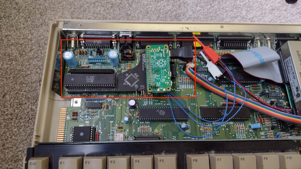
Finding the correct hardware is actually a little tricky. There are various options external to the box to convert a RGB signal into HDMI, but it seems like the best output and neatest is to use a hardware addon inside the box. It’s only recently that the audio breakout has been added, so I wanted to get this as well rather than requiring yet another adapter to get audio or separate speakers. The basic idea is that the Amiga 500 ‘Denise’ video chip is removed, and replaced by a breakout board which has the Denise chip plugged back into that, along with a raspberry pi zero which outputs the HDMI signal. The audio is taken from the existing audio circuitry on the Amiga and back into this breakout board. I got mine with the audio board pre-soldered to the main breakout board, but https://retrosupplies.co.uk/ have stopped selling these now. Their instruction booklet supplied with the board (Rgb2hdmi instructions) was pretty helpful though.
Step 1 – Flash SD card
https://github.com/IanSB/RGBtoHDMI/releases – I got the latest release and flashed it to the SD cards – specifically said it has support for audio included.
Step 2 – Disassemble Amiga & remove Denise Chip
After a moments hesitation on breaking the warranty seals (I guess its 40 year old now!), I unscrewed the case and removed the plastic top, and metal RF shield. Then I could get to the Denise video chip and remove it from its socket.
Step 3 – Insert Denise chip & Raspberry Pi into breakout board
This chip then goes back into the breakout board, along with the Raspberry Pi zero with the SD card and mini-hdmi to full size cable adapter.
Step 4 – Insert assembly into Amiga, solder audio connections
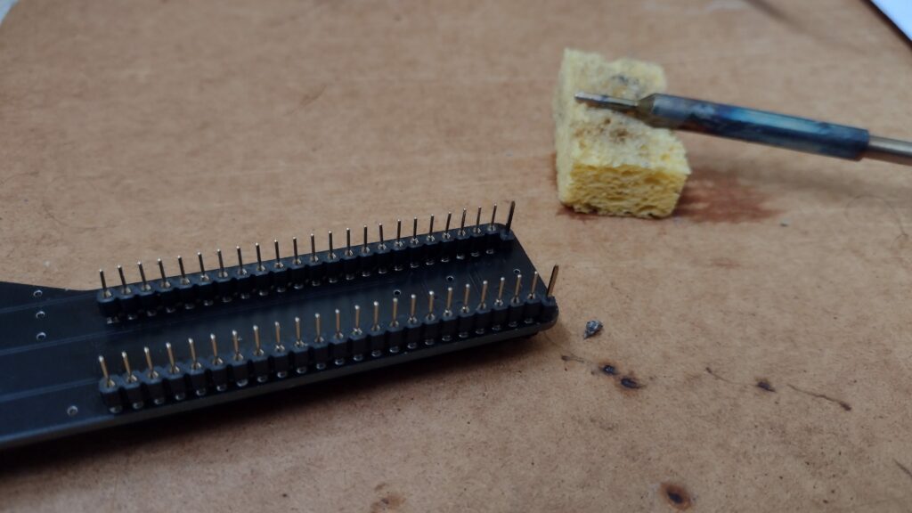
The kit was supplied with some clips for the jumper cables to the audio circuitry, but they were a bit weak and so I decided to solder them directly. Inserting the breakout board into the original Denise socket was fine – but having to remove it two or three times for later debugging was not – the pins were very delicate (round / turned pin) and I ended up breaking two or three of them and having to resolder some thicker ones instead (square IC pins 0.5mm) – which were more appropriate for this type of (lead DIP) socket as well.
Step 5 – Test
At this point, I plugged the Amiga into a monitor – it seemed like the motherboard was dead, but the mod had worked – it was powering the Raspberry Pi, so I got the on screen display of the breakout board through the HDMI connection (so 5v power getting through) but nothing from the Amiga itself – see Part B – debugging a dead motherboard if you want the extended details and how ChatGPT performed in this task!
Having fixed that, the mod mostly worked except the picture was completely distorted flickering in the horizontal direction. At this point ChatGPT suggested to check all connections to the breakout board and the motherboard. Sure enough, wiggling it about left me with a good picture but it took a lot of trial and error to find the right position. Probably the densie chip socket needed replacing, since even bending the pins in a little in the socket didn’t help that much, so i just found a good spot and left it there.
There was still some horizontal flickering, which seemed to be related to the and having looked at the instruction manual and done the auto-calibration, and then manually messing with the sampling settings with no benefit, I was scratching my head … until I finally noticed the profile was set to ‘BBC Micro’, switching it to ‘Amiga’ and it worked perfectly! Fixed! It should have been obvious, but it wasn’t explicitly in the instruction booklet, so I missed it – a good learning point for writing technical docs – don’t assuming anything, and include all details of every step!
Part B – Debugging a dead motherboard
The Amiga 500 initially failed to boot: the green power LED lit briefly and then went out, with no floppy activity.
I’m not really a hardware expert but I am used to debugging software and can do some basics with a soldering iron and multimeter – so this was a good project to have a go at with the help of LLM, ChatGPT v5.3 in particular – this was a good test to see how it performed in such a task.
This is ChatGPT’s summary of the conversation with my edits, comments and conclusion:
1. Power supply
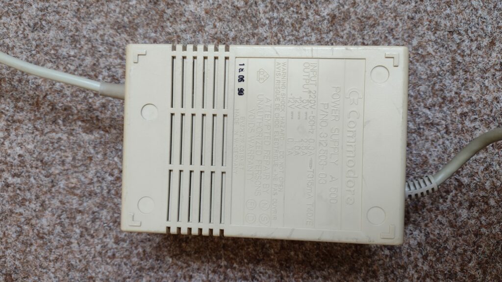
Early troubleshooting focused on the power subsystem because I reported that the PSU had previously made a buzzing noise. ChatGPT suggested that the Commodore Amiga 500 Power Supply might be failing and recommended testing or replacing it. In retrospect, this was incorrect. Measurements later confirmed the PSU output was stable, and the power supply turned out not to be related to the fault.
[Not impressed by that! Cost me 2 weeks and £70 – but a descent PSU is not a bad thing]
2. Voltage checks and Gary Chip
From there, ChatGPT guided me through checking the CPU and bus signals on the Motorola 68000 CPU. I measured CPU pin 15 (clock) and got about 1.4–1.5 V, which suggested clock activity. I measured CPU pin 18 (/RESET) and got 5 V, confirming reset was released. I also measured CPU pin 6 (/AS) and at one stage saw it low, and later about 1.6 V, which indicated bus activity rather than a dead CPU. I measured CPU pin 10 (/DTACK) and got 5 V, which suggested the CPU was not receiving acknowledge. ChatGPT interpreted this as a bus handshake problem.
ChatGPT then suggested checking Gary, because Gary is involved in bus control and expansion override signals. I measured Gary pin 24 = GND and Gary pin 48 = +5 V, so Gary had power. I then traced CPU pin 10 (/DTACK) to Gary pin 12, and measured Gary pin 12 at 5 V steady, meaning DTACK was not being generated. Based on that, ChatGPT suggested Gary might be faulty, and I replaced the Gary chip. That turned out to be another wrong turn: replacing Gary changed nothing, so Gary was also a red herring.
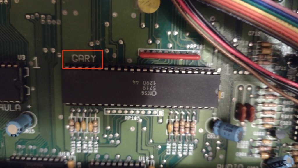
[I would have no idea about these details so I was basically blindly following ChatGPT with my multimeter at this point. I was a bit suspicious whether or not it was hallucinating or giving me the right pin numbers on the chips, but it seemed to find there was an issue with the Gary pin. That cost me another week and another 20 quid! At this point I was kind of all in anyway, so I kept going…]
3. Short Ciruit
Despite that incorrect conclusion, the process of investigating Gary and the /OVR line proved valuable. By measuring continuity and resistance between Gary pin 29, the expansion connector, and nearby resistor networks, it became clear that the /OVR line behaved as though it were partially pulled toward ground. This suggested a board-level short or leakage rather than an IC failure.
With the CPU temporarily removed to isolate signals, further resistance checks were performed along the /OVR net.
Continuity tracing from Gary pin 29 to the side expansion connector and nearby resistor pack pins narrowed the suspected region of the fault. Visual inspection of the solder side of the motherboard eventually revealed the true cause: a small solder blob bridging traces on the underside of the board along the /OVR signal path.
[This was a very interesting electronics debugging step that learned – if something along a line is pulling it to ground in between two points, just check the continuity to ground at every component on that line – and I found a solder blob from a component bridging onto that line – it obviously had worked fine for 40 years despite it being present, but perhaps when I took it apart it had gotten squashed onto the lines making the short]
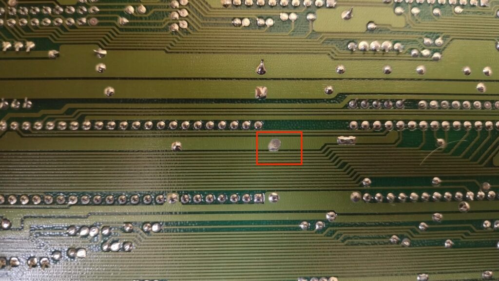
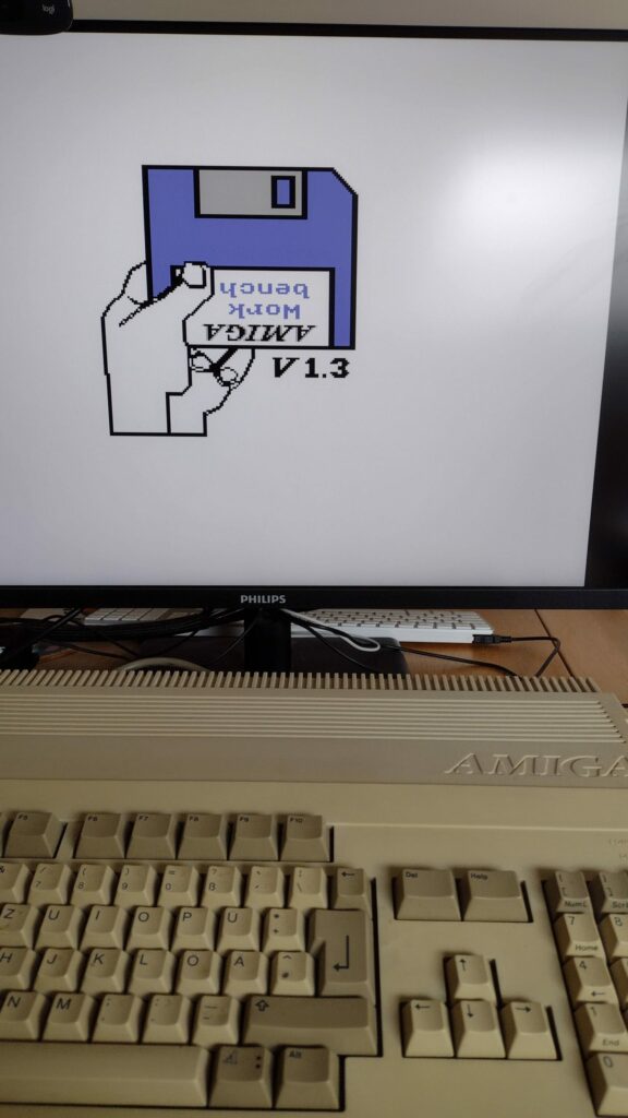
Once the solder bridge was removed, the abnormal voltage on the /OVR line disappeared and the signal returned to correct logic levels. After this fix, the Amiga successfully progressed through the boot sequence and displayed the Kickstart insert-disk screen, confirming that the core bus control logic was now operating correctly. The earlier suspicions about the PSU and the Gary chip were therefore both incorrect; the entire failure had been caused by a simple solder short on the motherboard.
4. Conclusion
Despite being frustrated by two red herrings costing me real £money, I would not have been able to debug that on my own without ChatGPTs help. It definitely required my persistence, debugging skills, accurate description and knowing how to drive the LLM, but as a tool it worked pretty well to (eventually) solve the problem – and I learned something through the process as well. And now my wife can play Monkey Island….?!
Leave a Reply